
This process is used on Dimension One Spas with a “Trombone” style heater from 1998-2014. The photo shows a typical example of the equipment layout for a 2-pump system.
You’ll need to shut off power at the GFI and drain the spa to get started.
Step 1
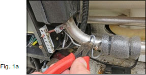
Cut the zip tie holding the High Limit Sensor in place. (Fig 1a)
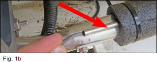
Slide the High Limit Sensor out from under the pad. (Fig 1b)
Step 3
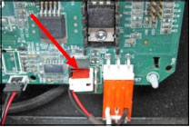
Unplug the flow switch connector from the PC Board. Please call us if you need help locating this connector.
Step 5

Cut the 4 heater wires where they enter the metal equipment box. (Fig 5a)
Disconnect and remove the wires you’ve just cut.
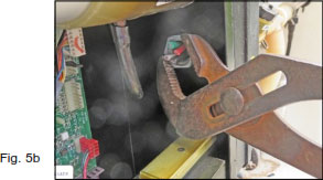
Unscrew and remove the thin nut holding the plastic heater box to the metal equipment box. (Fig 5b)
Step 7
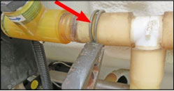
Loosen and slide the clamp to the right of the flow switch. (It only needs to move about 1 ½”.)
Step 9

Separate the flow switch from the hose.
The heater assembly is now loose and can be removed. You’ll have to be a little creative and use some muscle to get the assembly out. Just be patient and you’ll figure something out.
Step 11
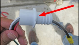
The new heater has an adapter that you won’t need for this installation. Remove and dispose of the adapter.
Step 13
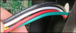
Align the new heater in place. Feed the 4 wires through the metal box.
Step 15
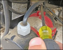
Align the new heater in place. Feed the 4 wires through the metal box.
Step 17
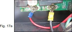
Attach the new heater wires to the circuit board. (Fig 17a)
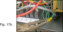
Attach the ground wire to the grounding nut inside the metal box. (Fig 17b)
Step 19
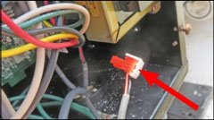
Plug the flow switch connector back on the PC Board.
Step 21
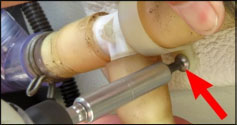
Reattach the nylon clamp from Step 2.
Congratulations, your installation is complete. Fill the spa with water and turn power back on at the GFI.
Step 2

Remove the nylon clamp holding the hose in place.(Fig 2a)
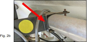
Remove the metal bracket holding the heater tube in place. (Fig 2b) You won’t need to replace this metal clamp later. The heater will stay in place without it.
Step 4
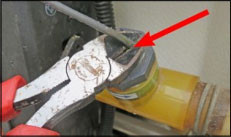
Cut the flow switch wire at the top of the switch. Throw the cord away.
Step 6
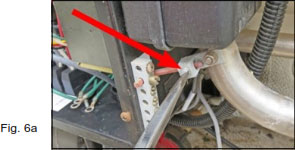
Remove the wire between the heater lug and grounding lug. (Fig 6a)
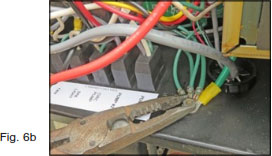
Remove heater grounding wire at grounding screw. (Fig 6b)
Step 8

Loosen hose clamp where lower heater hose attaches to the circulation pump. (The middle of this pump can be red, blue or black).
Step 10


Set the old heater next to the new heater as pictured.
Move the short piece of hose from the bottom of the old heater tube, to the new heater.
Step 12
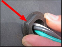
Remove the plastic nut from the outside of the new heater box and throw it away.
Step 14
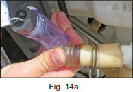
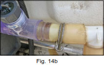
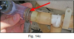
Attach the new flow switch tee to the old hose. (Fig 14a & 14b) Slide the hose clamp back to the left and back in place. (Fig 14c)
Step 16
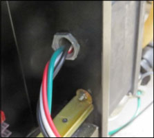
Thread the 4 heater wires through the mounting nut and tighten it in place.
Step 18
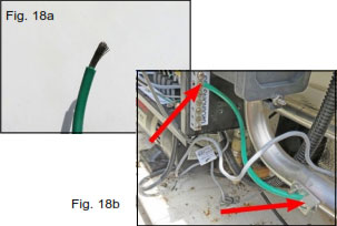
The grounding lug on the new heater tube is in a different position so we’ll have to make our own new ground wire to attach outside the box. Taking the original green wire from the old heater, cut a piece 6” long. Remove about ¾” of insulation from each end, (Fig 18a), and twist the wire strands.
Attach one end onto the heater lug and the other on the grounding bar as pictured, (Fig 18b).
Step 20
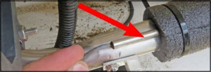
Side the High Limit Sensor under the new foam pad on your heater.
Please call if you have any questions
(866) 418-1840 toll free in the US

